

Military small-craft systems integration brings power, data, mission equipment, and crew workflows together as an installed system. This guide explains what to check during interface planning, installation, testing, and acceptance.
Written by Scott Dunnicliff.
Equipment can work correctly on the bench and still fail when installed, powered, networked, and operated at the same time aboard a craft. Small-craft integration therefore covers electrical capacity and protection, physical installation, environmental exposure, maintainability, equipment interfaces, and operator use under real conditions.
Power and electrical integration
Start with the craft’s actual electrical architecture. Build a load list that identifies each item’s supply-voltage range, steady-state demand, peak demand, and startup current, then compare it with generator, battery, converter, and distribution capacity. Include equipment that operates intermittently or changes state during a mission. Size conductors for load and run length, then calculate voltage drop at the equipment terminals rather than relying only on the source rating. Verify the result with the equipment operating in its expected configuration, not only with an unloaded circuit.
Each circuit needs suitable protection, isolation, and a safe means of disconnection. Review breaker or fuse ratings, inrush behavior, local disconnects, grounding and bonding, and the intended return path. Poor returns, shared conductors, loose terminations, and undersized wiring can cause noise, intermittent operation, or undervoltage. Routing must also account for vibration, spray, heat, interference, and maintenance access.
Engine or propulsion loads do not automatically reduce electronics supply voltage. Starting motors, alternators, pumps, thrusters, and other dynamic loads can introduce disturbances when the distribution design, battery condition, regulation, or return paths allow them to reach electronics. A radio that reboots during a measured voltage dip indicates a supply problem; a powered display with no new position data points instead toward a source, data path, configuration, or processing problem.
Data and equipment interfaces
Define every required information path by source, destination, physical medium, electrical characteristics, protocol, messages, configuration, and update rate. Record which system provides the authoritative source for each required datum and what the receiving equipment should do when that datum is unavailable. A connector that fits is not proof of compatibility. Systems may use serial links, discrete signals, radio, dedicated interfaces, or Ethernet; sensor feeds do not all use Ethernet, and navigation, communications, and control systems do not have to share one network. Confirm pin assignments, signal levels, addressing, message settings, and update expectations before installation.
Test the complete path, not only whether a component starts. Data loss, stale data, excessive latency, corrupted or misconfigured messages, and total equipment failure have different symptoms and responses. Confirm what the operator sees when a source, link, switch, processor, or display fails, and verify alarm timing, meaning, and recovery. The NIST Cybersecurity Framework can structure cybersecurity risk management; it is not a marine installation standard, certification, or proof of compliance.
Define dependencies between power, data, installation, environmental exposure, and operator tasks. A replacement module must meet the platform’s electrical, data, physical, environmental, and operational requirements. Changes can affect loading, cooling, timing, network behavior, or crew procedures elsewhere in the installation, so updates require targeted retesting.
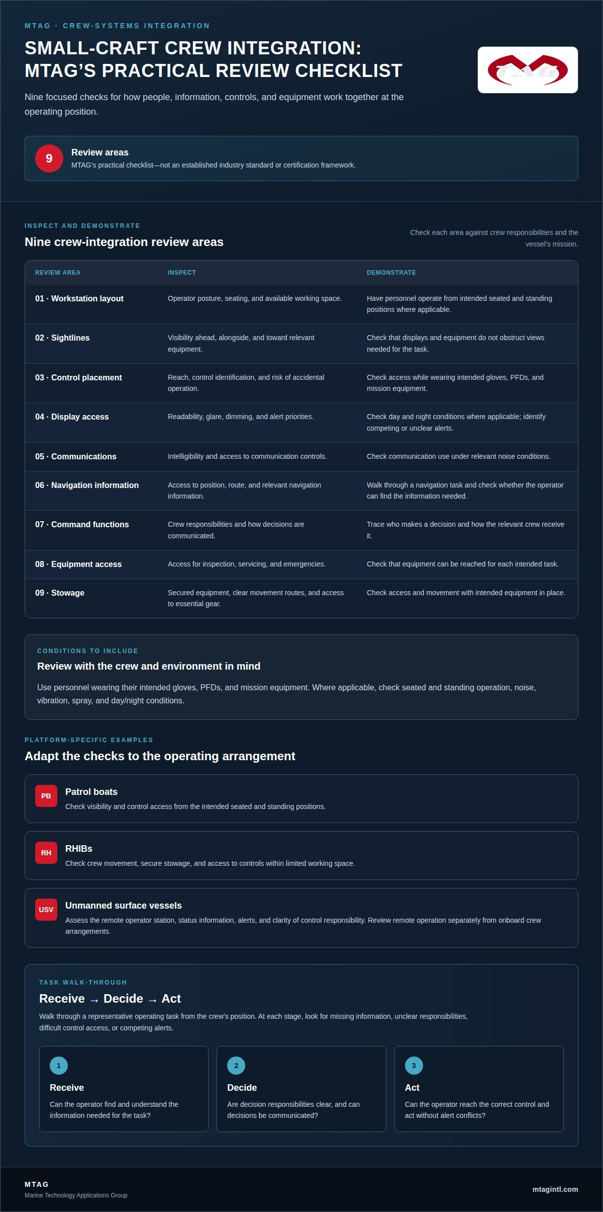
Crew layout and operation
Arrange the installation around the operator’s actual position and tasks. Check forward and lateral sightlines, display readability in expected light, control reach while seated or standing, and operation with gloves or wet hands. Put high-priority alarms where they are visible or audible without abandoning the primary task, and distinguish warnings requiring immediate action from information that can wait.
Review the complete sequence: receiving information, deciding, using a control, confirming the result, and responding to a fault. Navigation, communications, and observation equipment may compete for space, power, and attention. Secure stowage, cable protection, ventilation, and maintenance access are part of the usable design. Crew readiness also requires a defined degraded mode and the ability to identify whether a fault is electrical, data-related, or equipment-specific.
Testing and acceptance
Installation checks confirm that equipment is mounted, wired, protected, labeled, and accessible. Functional tests then verify startup, controls, displays, alarms, data paths, and recovery at the dock. Measure voltage at the load during starting and dynamic events, and test loss and restoration of power or data so a supply disturbance is not misdiagnosed as a network failure. Record the test configuration and observed behavior, including which equipment was operating and which indicators or alarms appeared. These records establish a useful baseline for troubleshooting after underway trials or later configuration changes.
Underway testing should exercise vibration, motion, environmental exposure, electrical load changes, and the crew’s real tasks. Deliberately test recovery, alarm visibility, display readability, control reach, and defined degraded modes. Record whether information is absent, stale, delayed, or wrong, the operating condition, consequence, corrective action, and retest result. Acceptance criteria come from the program’s requirements and acceptance process; acceptance testing is not the same as certification.
Marine Technology Applications Group: Maritime Systems Integration
Marine Technology Applications Group supports small-craft programs with maritime systems integration focused on platform interfaces, electrical and data dependencies, crew layout, and verification of installed functions. MTAG can help turn mission requirements into documented interfaces, practical test conditions, and an installation operators and maintainers can use. Contact Marine Technology Applications Group to discuss a small-craft integration requirement.
Written by Scott Dunnicliff.
Https://www.mtagintl.com
Related MTAG capability: small-craft electrical, power and network integration

