

Written by Scott Dunnicliff.
The simplest small-craft mission system architecture is not always the lowest-risk choice. Compare each design against mission-success criteria, then weigh cost, schedule, element reliability, and onboard capability. Begin with the concept of operations, which describes how the craft and its systems are intended to perform the mission.
Every added interface, sensor, network, or power demand affects integration and operator workflows. A structured comparison brings these dependencies into view early, before they become fielding problems.
This article explains how to compare architecture options against mission needs, identify cost and schedule drivers, and assess failure risks across connected systems. It also shows how to define success criteria and trace requirements through verification and validation, keeping design decisions tied to the mission rather than to an equipment list.
Key takeaways
- Compare architecture options by tracing how component reliability, integration complexity, and operational demands affect cost, schedule, and failure exposure.
- Assess distributed designs by considering deployment approach, coverage needs, and the coordination required across craft and mission elements.
- Turn mission-success criteria into measurable requirements, then connect each requirement to a method for validation and verification.
- Align onboard sensing, diagnostics, and control with operator workflows so the system supports decisions without creating unnecessary integration burden.
Cost, schedule, and failure-risk trade-offs
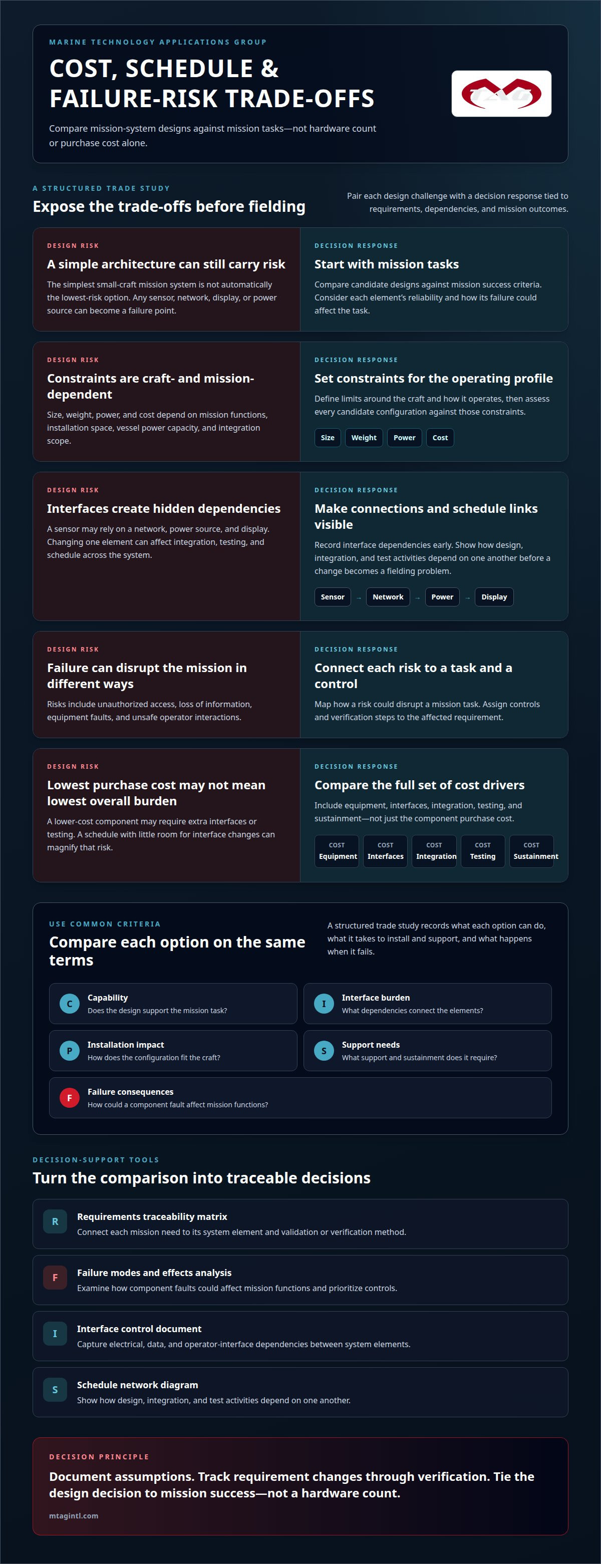
Compare designs against mission tasks before selecting hardware. A small-craft mission system architecture must account for the reliability of every element: a sensor, network, display, or power source can become a failure point. The concept of operations also shapes performance. A system designed for one operator’s workflow may require different interfaces from one supporting a separate watch team.
Size, weight, power, and cost requirements depend on mission functions, installation space, vessel power capacity, and integration scope. Set constraints from the craft and its operating profile, then assess each candidate configuration against them. Cost drivers include equipment, interfaces, integration, testing, and sustainment.
Cybersecurity, safety, and reliability risks include unauthorized access, loss of information, equipment faults, and unsafe operator interactions. Map each risk to the mission task it could disrupt, then assign controls and verification steps to the affected requirement.
Use a structured trade study to record each option’s capability, interface burden, installation impact, support needs, and failure consequences. Identify dependencies early. A sensor that relies on a network, power source, and display creates several integration points, so changing one element can affect testing and schedule across the system.
- Requirements traceability matrix: Connect each mission need to its system element and validation or verification method.
- Failure modes and effects analysis: Examine how component faults could affect mission functions and prioritize controls.
- Interface control document: Capture electrical, data, and operator-interface dependencies between system elements.
- Schedule network diagram: Show how design, integration, and test activities depend on one another.
Compare options using common criteria, not purchase cost alone. A lower-cost component may increase integration effort if it requires extra interfaces or testing. A schedule with little room for interface changes can magnify that risk. Document assumptions and track requirement changes through verification. The result is a defensible decision tied to mission success, not a hardware count.
Distributed architectures, constellations, formations, and swarms
Distribute functions when one craft’s sensors, operators, or communications cannot meet mission needs alone. A networked group can share selected information, divide observation tasks, or preserve functions when one node is unavailable. Each added node also brings coordination and interface demands. Define what information must move, who uses it, and what happens if a connection fails.
For a U.S. Navy or USMC small-craft scenario, compare a single-craft arrangement integrating navigation, communications, observation, and command displays with a distributed arrangement that shares selected information across craft. These are architecture patterns for comparison, not named fleet programs. Open, modular architectures support change through defined interfaces and replaceable components. Integration can simplify coordination among tightly connected functions, but a change may affect more of the design.
Size the group and deployment approach to the mission. Craft operating together have different coordination needs from craft deployed individually or in batches. A swarm also depends on decision rules: which tasks are shared, how priorities are assigned, and how operators retain control. Define behavior during communication loss before selecting links or interfaces. If a design depends on continuous data exchange, specify a fallback for interrupted connections.
- Mission-thread diagram: Shows how information moves among craft, sensors, networks, and operators.
- Interface control document: Defines the data and connection boundaries between modular elements.
- Operational scenario matrix: Compares all-at-once, batch, and individual deployment against mission tasks.
- Network topology diagram: Clarifies which nodes exchange information and where a failure could isolate a function.
Use these tools to compare coverage, coordination burden, and graceful degradation, meaning continued useful operation after a node or link fails. Record each design’s assumptions, including operator workload and communication availability. A practical trade study should test normal operations and disconnected cases. For a craft-level design that must align sensors, networks, power, and command functions, maritime systems integration is a relevant next step.
Mission success criteria
Set mission-success criteria before selecting system functions. Criteria should describe operational results, such as detecting a target, sharing a report, or maintaining command awareness when a data link is unavailable. Keep them current as mission priorities change, and trace programmatic and technical decisions back to these outcomes.
Applicable standards and regulations depend on the craft, mission, acquisition, and operating context. Build an applicability matrix listing each governing requirement, its design impact, and the evidence needed to demonstrate compliance. This makes assumptions visible and helps prevent applying a standard outside its scope.
Design and integration should follow a traceable sequence: define the concept of operations, derive requirements, allocate them to system elements, integrate interfaces, then verify and validate performance. For example, a requirement to share an observation report needs a defined operator, data path, and test method.
- Concept of operations: Describe mission phases, operators, information needs, and degraded conditions.
- Requirements traceability matrix: Link each mission criterion to system requirements, design elements, and verification methods.
- Verification cross-reference matrix: Identify inspection, analysis, demonstration, or test evidence for each requirement.
- Test procedures: Define conditions, inputs, expected outputs, and pass criteria before execution.
Distinguish a desired capability from an acceptance criterion. “Provide observation” is too broad. A stronger requirement identifies what information reaches which operator, under what operating conditions, and how the result will be assessed. Avoid criteria that measure equipment presence alone; installing a sensor onboard does not, by itself, establish mission success.
Review criteria at each design gate. Confirm that every changed requirement still supports the mission and has a practical verification method. During integration, test complete mission threads, not just individual components. For example, validate that an observation travels from the sensor through processing to the intended operator display. Record results against the requirement, resolve failures, and repeat the relevant test before acceptance.
For small-craft missions, keep success criteria clearly defined and current throughout the effort. Use them to guide programmatic and technical decisions, anchoring choices to intended mission outcomes. When priorities or assumptions change, revisit the criteria and the decisions based on them.
Onboard sensing, diagnostics, and control
A small-craft mission system brings together sensors, navigation, communications, networks, power, and command-and-control interfaces. Operators use these elements to observe conditions, exchange information, and direct mission tasks. Required components depend on the mission thread, not on a standard equipment list.
Integration defines how information moves between components. Navigation data, for example, can provide context for an observation, while a network carries the report to an operator display. Specify the data, purpose, and destination for each connection. Then identify which functions remain available if a sensor, network path, or display becomes unavailable.
Diagnostics should give operators and maintainers useful information about system state. A fault indicator might identify lost sensor input or a power interruption. Define the condition that triggers each indication, where it appears, and what action follows. Separate actionable faults from routine status updates so they do not obscure mission-critical alerts.
- Data-flow diagram: Maps information paths from sensor input to operator display or command action.
- Interface control document: Records the connections and data exchanged between system elements.
- Fault tree analysis: Traces how component faults could interrupt a defined mission function.
- Human-machine interface review: Assesses whether operators can interpret system status and act through the intended controls.
Test complete operator workflows, not only individual devices. A representative test could follow a navigation cue, sensor observation, network transfer, and display presentation. Record whether each element performs its assigned function, then test how the workflow responds to a lost data path. This can reveal integration faults that component checks alone miss.
For small craft, installation constraints also affect sensing and control. Equipment placement can influence visibility, access, cable routing, and operator movement. Assess these relationships during design, then confirm them during onboard integration and operational testing. Plan maritime systems integration around the craft’s sensors, networks, power, and command functions.
Marine Technology Applications Group: Maritime Systems Integration
Marine Technology Applications Group integrates mission systems for military small craft, connecting sensors, networks, power, and command-and-control functions. Its maritime systems integration capability supports programs that need to translate mission requirements into a coherent onboard architecture or connect separate subsystems through defined interfaces.
This work is especially relevant when design decisions affect operator workflows, system dependencies, or fielding. Maritime ISR Integration supports intelligence, surveillance, and reconnaissance missions. Tactical Coxswain Training addresses the operator side of mission execution, while Defense Maritime Consulting supports broader maritime planning and technical decisions.
Bring your mission tasks, operating context, and current system boundaries to the discussion. Discuss your maritime systems integration requirement with MTAG.
Carry the architecture into execution
The next step is turning mission priorities into an executable engineering baseline. Keep the small craft mission system architecture tied to operator tasks as requirements mature, interfaces are defined, and integration plans take shape. This gives technical teams a clear reference when design changes affect mission functions.
Marine Technology Applications Group provides Maritime Systems Integration, Tactical Coxswain Training, and Defense Maritime Consulting. These services address connected system design, operator readiness, and broader maritime planning. Matching the work to the program’s current phase helps keep engineering decisions connected to operational use.
Bring forward the mission tasks, current system boundaries, and unresolved integration decisions. Contact MTAG to discuss the next step. A disciplined baseline gives the team a practical foundation for moving from architecture toward fielded capability.
Frequently asked questions
What is a small-craft mission system architecture?
It is the arrangement of onboard equipment, software, interfaces, and operator roles that enables a craft to perform mission tasks. An architecture, for example, can define how a sensor observation reaches a command display and how an operator acknowledges it. It also establishes which functions are local, which rely on network connections, and how the crew manages degraded capability.
What are common mission system architectures for small boats and unmanned surface vessels?
Common patterns include centralized systems, modular systems, and distributed networks. A centralized design routes information through a primary control element. A modular design separates functions behind defined interfaces, making components easier to change with less disruption. A networked unmanned surface vessel may share selected data with a remote control station or other craft. The mission determines which pattern best fits the required autonomy and operator oversight.
What standards and regulations apply to small-craft mission system design?
Applicable standards and regulations depend on the craft, mission, acquisition, and operating context. Record each applicable requirement, its design impact, and the evidence needed to demonstrate compliance in an applicability matrix.
What are examples of small-craft mission system architectures used by the U.S. Navy or Marine Corps.
The article compares a single-craft arrangement integrating navigation, communications, observation, and command displays with a distributed arrangement that shares selected information across craft. These are architecture patterns for comparison, not named U.S. Navy or Marine Corps fleet programs.
